Designing detectors and collimators
When the shipped camera presets do not match what you want to study, you can build the
collimator and detector yourself. You set their materials, dimensions, and design entirely in the
OpenTOPAS parameter file, with no C++, and you can load CAD-designed parts for shapes the parametric
classes do not cover. Worked decks for everything below are in
examples/design/.
Every geometry is a standard OpenTOPAS component. Set s:Ge/<name>/Type to the class, give it a
Parent, a Material, its design parameters, and a placement (TransX/Y/Z, RotX/Y/Z), then attach
any scorer with s:Sc/<scorer>/Component = "<name>".
Collimators
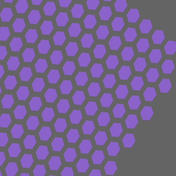 A
A TsParallelHoleCollimator with hexagonal holes on a hexagonal lattice (OpenTOPAS geometry view).
| Design | Class | Use |
|---|---|---|
| Parallel-hole | TsParallelHoleCollimator |
LEHR/ME/HE clinical SPECT; round/hex/square holes |
| Converging (fan/cone-beam) | TsParallelHoleCollimator with a focal length |
brain SPECT, magnification |
| Pinhole / multi-pinhole | TsPinholeCollimator |
thyroid, preclinical, cardiac |
| Slit-slat | TsSlitSlatCollimator |
hybrid CZT systems |
Parallel-hole and converging: TsParallelHoleCollimator
A regular hole array. The parameters (see the
README for the full table) are
HoleDiameter (flat-to-flat), SeptalThickness, CollimatorLength, NHolesX/Y, HoleShape
(Round/Hex/Square), Lattice (Square/Hex), Material, and Hole/Material.
To make the collimator converge, set FocalLengthX and/or FocalLengthY, the distance from the
collimator face to the focus. Each channel then tilts toward that focus:
- both finite gives a cone-beam collimator converging to a point;
- one finite gives a fan-beam collimator with a focal line;
- a negative value gives a diverging collimator;
0(the default) gives a parallel collimator.
A converging collimator magnifies by m = f / (f − z) for a source at distance z. See
converging_conebeam.txt.
Pinhole and multi-pinhole: TsPinholeCollimator
An absorber plate with one or more knife-edge (double-cone) apertures. The parent volume (vacuum) fills the aperture. Keep the plate large enough to cover the detector field of view, so photons reach the crystal only through the pinhole(s).
| Parameter | Meaning |
|---|---|
Material |
plate/absorber (for example Lead, Tungsten) |
PlateThickness |
absorber thickness (z) |
PinholeDiameter |
aperture diameter at the knife edge |
AcceptanceAngle |
full opening angle of the double cone (default 90 deg) |
NPinholesX, NPinholesY |
pinhole grid (default 1×1, a single pinhole) |
PinholePitch |
center-to-center pinhole spacing |
PlateHLX, PlateHLY |
plate transverse half-size (default covers the grid plus one pitch) |
FocalLength |
0 for axial pinholes; finite to aim each pinhole at an object-side focus |
A pinhole magnifies by m = l / h and inverts the image. See
pinhole.txt and
multipinhole.txt.
Slit-slat: TsSlitSlatCollimator
An absorber slab with a stack of rectangular through-slots: a slit aperture in the transaxial (x) direction crossed with parallel slats in the axial (y) direction.
| Parameter | Meaning |
|---|---|
Material |
absorber (slat) material |
CollimatorLength |
slab thickness (z) |
SlatThickness |
absorber foil thickness between slots (y) |
SlatGap |
open slot height (y); slat pitch is SlatThickness + SlatGap |
NSlats |
number of open slots |
SlitWidth |
slot width in x, the slit aperture |
Slot/Material |
slot fill (for example Vacuum) |
See slitslat.txt.
Detectors
| Detector | Class |
|---|---|
| General pixelated detector | TsPixelatedBox (native OpenTOPAS) |
| Continuous crystal slab | TsBox (native OpenTOPAS) |
| GE StarGuide CZT | TsStarGuideDetector (this package) |
For a general pixelated detector, use the native TsPixelatedBox: you choose the pixel material,
size, pitch, and count. The parameters are Material (frame), Pixel/Material, NumberOfPixelsX/Y,
PixelSizeX/Y/Z, and PitchX/Y. Attach a scorer to the component name
(Sc/.../Component = "Det"). Ready-to-include crystal fragments are
systems/detector_nai.txt
and
systems/detector_czt.txt;
a worked example is
pixelated_detector.txt.
CAD import for novel geometries
To model a shape the parametric classes do not cover, design the part in any CAD editor, export it as
binary STL or ASCII PLY, and load it with the native TsCAD component:
s:Ge/Part/Type       = "TsCAD"
s:Ge/Part/Parent     = "World"
s:Ge/Part/Material   = "NaI"
s:Ge/Part/InputFile  = "path/to/part"   # extension added from FileFormat
s:Ge/Part/FileFormat = "stl"            # "stl" (binary), "ply" (ascii), or "tet"
d:Ge/Part/Units      = 1.0 mm
See cad_component.txt
(with a sample cube.stl).
Use CAD for detector housings, pinhole plates, shields, and novel single-piece bodies. Do not mesh
a fine multi-hole collimator: 10⁴–10⁵ holes become millions of triangles and navigation slows to a
crawl, so use the parametric TsParallelHoleCollimator for hole arrays instead. The mesh must have
consistent outward-facing facet normals; without them G4TessellatedSolid cannot tell inside from
outside, and photons pass through as if the part were empty.
Recommended CAD tools
TsCAD reads standard interchange formats, so any tool that exports them works. This package bundles
no CAD software; the free, open-source toolchain below keeps the workflow at zero cost.
| Tool | Role | Output |
|---|---|---|
| OpenSCAD / CadQuery | script-based parametric CAD; the design is a text file you version alongside the deck, good for pinhole plates, housings, shields, and novel single-piece bodies | STL (CadQuery also STEP) |
| FreeCAD | GUI parametric mechanical CAD, Python-scriptable | STL |
| Gmsh + TetGen | volumetric/tetrahedral meshing for the TET path (.node/.ele) |
TET |
| 3D Slicer | segment medical imaging into a mesh (anthropomorphic phantoms) | STL |
| MeshLab or Blender (3D-Print toolbox) | repair and validate the mesh: make it watertight and manifold with outward normals | STL/PLY |
Commercial packages (Fusion 360, Onshape, SolidWorks, Inventor) also export STL and work fine if you already have them.
Follow this export checklist with any tool: (1) export binary STL or ASCII PLY (or TetGen
.node/.ele); (2) model in millimeters and set Ge/<name>/Units = 1.0 mm; (3) run a repair and
validation pass (MeshLab "Repair non-manifold", or Blender "Make Manifold") so the mesh is watertight,
manifold, and outward-normal; (4) reserve CAD for housings, plates, and novel single-piece parts, and
use the parametric collimators for hole arrays.
Materials and dimensions
Any component's material is s:Ge/<name>/Material = "<element-built or NIST material>". Build custom
materials from elements (Ma/<name>/Components + Fractions + Density). OpenTOPAS predefines the 88
standard element symbols (Lead, Tungsten, Cadmium, Zinc, Tellurium, Sodium, Iodine, and
so on). All dimensions are plain length parameters, so you change them freely.
Attaching scorers
The package scorers work on any of these geometries:
EDepSpectrum(TsEDepSpectrum) records the per-event deposited-energy spectrum and the interaction centroid; attach it to the crystal or detector component.StarGuideProjection(TsScoreStarGuideProjection) records a pixel-binned projection with Gaussian energy smearing, binning by local position, and works on any box crystal.ForcedDetectionProjection(TsForcedDetectionProjection) is the analytic-collimator fast path for variance reduction.
Not yet included
Exact-solid CAD exchange through GDML (solids, materials, and hierarchy together) needs a Geant4 build compiled with GDML/XercesC, which this build omits; using it would mean rebuilding Geant4. The STL/PLY mesh import above covers the CAD workflow in the meantime.